No Questions from the Shop Floor.

Every drawing package we issue contains everything the fabricator needs: dimensions, tolerances, weld details, material specifications, and fabrication notes. We work to the project's drawing standard and adapt to the client's document management system.

Before issue, every drawing goes through a structured independent check. Not a read-through, but a systematic verification against the design inputs, calculation outputs, and applicable standard. Dimensions are cross-checked against the model, weld symbols verified against the WPS, nozzle schedules reconciled against the equipment datasheet. By the time a drawing leaves us, it has been interrogated, not just reviewed.

Modelling Approach

A structured parametric workflow that ties 3D geometry directly to design intent, so drawing updates follow automatically from model changes.

01
Design Input

Parametric 3D Model

Most modelling errors are not drafting mistakes. They are geometry that appears correct but breaks downstream. Fully constrained parametric models, where every dimension is driven by design intent, eliminate this class of error. Where 3D modelling is not required, we work directly in 2D.
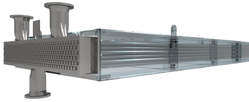
Parametric 3D model example
02
Documentation

Drawing Generation

Drawings not derived from the model introduce transcription errors, mismatched dimensions, and inconsistencies between views and assemblies. Every view, section, and detail is extracted directly from the 3D model, so drawings remain fully aligned with the design. For 2D-only scope, views are produced directly to the applicable drawing standard.
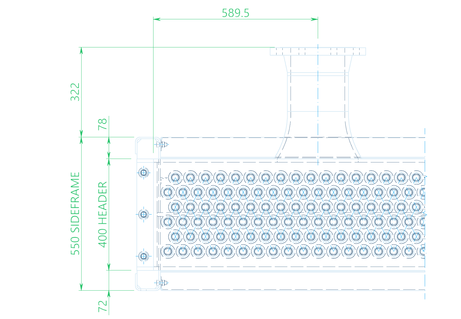
Parametric 3D model example
03
Annotation

Detailing & Tolerancing

Incomplete annotation is a primary cause of fabrication queries and shop floor delays. GD&T, weld symbols, surface finish, material callouts, and fabrication notes are applied to drawing standard. We work to the applicable code, specification, or client requirements.
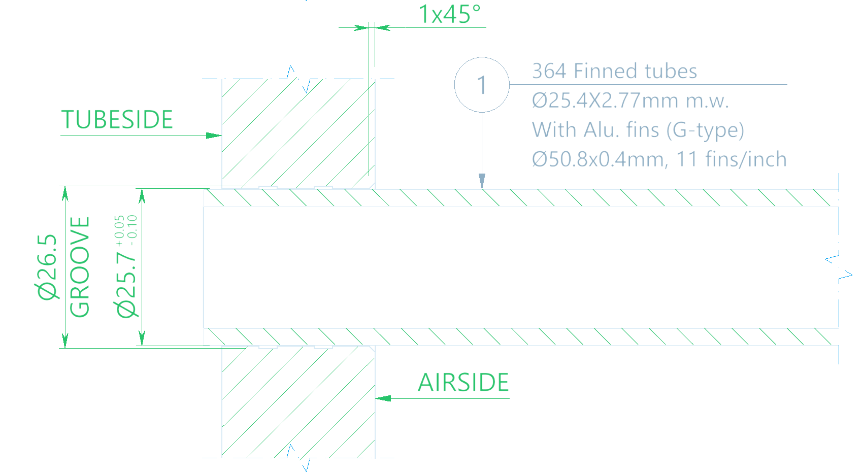
Parametric 3D model example
04
Issue

Review & Release

Drawings issued without internal checking place the burden of design verification on the fabricator, introducing cost and schedule risk. Every drawing package is checked before issue, released with revision status and transmittal record, and maintained through subsequent revisions. We align with the client’s document control and numbering system.
APPROVED
REV A
BY MECHNEX QC
CHECKED: 20 MAR 2026 QC ENGINEER: B.V. STATUS: APPROVED

Drawing Types

Drawing packages developed directly from controlled models, ensuring consistency between design, documentation, and fabrication. Standard deliverables tailored to the scope and stage of the project.

Design & Layout
  • General Arrangement (GA) drawings
  • Assembly drawings
  • Piping arrangement drawings
  • Structural arrangement drawings
  • Skid layout drawings
Fabrication & Documentation
  • Detail and part drawings
  • Weld maps and joint details
  • Piping isometric drawings
  • Bill of materials (BOM)
  • As-built documentation
Dimensioning & Tolerancing
ASME Y14.5 ISO 128 ISO 2768
Welding Symbols
AWS A2.4 ISO 2553
Output Formats
PDF DWG DXF STEP IGES